What is a Magnetic Mirror?
A magnetic mirror is one of magnetic confinement types for plasma. Plasma and magnetic confinement are explained in detail here.
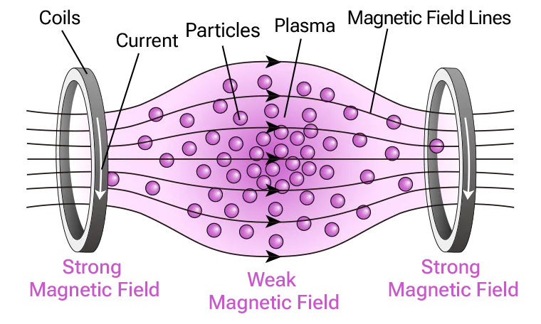
When two coils are placed coaxially and an electric current is passed through them in the same direction, a magnetic field configuration is formed as shown in the figure below, where the magnetic field is strong near the coils and weak between them. This is called a (simple) magnetic mirror. A characteristic feature of the magnetic mirror is its open magnetic field line structure (referred to as “open ends”).
The Confinement Principle of a Magnetic Mirror
When the strength of a magnetic field changes slowly in time and space, the magnetic moment μ (given by the following equation) of a charged particle moving in the magnetic field remains constant.

Where:
| m | mass of the charged particle |
|---|---|
| v⊥ | velocity component of the charged particle perpendicular to the magnetic field |
| B | strength of the magnetic field |
The principle of a magnetic mirror confinement is based on conservation of the magnetic moment and the kinetic energy.


Where:
| v|| | velocity of the charged particle parallel to the magnetic field |
|---|
When a charged particle moves to a region where the magnetic field B is stronger, the kinetic energy perpendicular to the magnetic field increases due to the magnetic moment conservation. Then, the velocity parallel to the magnetic field decreases due to the kinetic energy conservation. Under certain conditions, v|| becomes zero, and the charged particle is reflected back at the region of strong magnetic field, thus being confined. The phenomenon of charged particles being reflected at the strong magnetic field region, resembling light reflection by a mirror, is why it is called a “magnetic mirror.”
Now, let’s explain these “certain conditions.” Let Bm be the maximum magnetic field strength at position z >= zm (coil region), and B0 be the minimum magnetic field strength at position z = z0 (midpoint between the two coils). Let v⊥(z) and v||(z) represent the velocities of the charged particle perpendicular and parallel to the magnetic field at position z, respectively. From the conservation of magnetic moment:


Considering the kinetic energy perpendicular to the magnetic field at z = zm:

Which means:

When this condition is met, the charged particle cannot reach the position z = zm. (From the conservation of kinetic energy, if the above inequality holds, then mv||(zm)2 / 2 < 0, which implies a negative kinetic energy, a physically impossible.) The ratio Bm / B0 (ratio of the maximum magnetic field to the minimum magnetic field) in the above inequality is called the “mirror ratio.” From the above equation, the confinement by a magnetic mirror can be improved by either:
- Increasing the mirror ratio.
- Increasing the velocity of the charged particle perpendicular to the magnetic field.
Features of a Magnetic Mirror
(1) Confinement of High-Temperature Plasma
The Tandem Mirror device GAMMA 10 at the Plasma Research Center, University of Tsukuba, achieved confinement of high-temperature plasma at 10 keV (approximately 100 million degrees Celsius), which is necessary for inducing thermonuclear fusion reactions, as early as 1994. [1]
(2) Confinement of High-Energy Beam Ions
As mentioned in the section “The Confinement Principle of a Magnetic Mirror,” charged particles with a larger velocity component perpendicular to the magnetic field are more easily confined by a magnetic mirror. Therefore, high-energy beam ions (i.e., charged particles moving at high speed) with a large pitch angle relative to the magnetic field can be efficiently confined.
We aim to realize an advanced fuel fusion reactor based on “non-thermal fusion” rather than the commonly known thermal fusion. The key to occurring non-thermal fusion reactions is the confinement of high-energy beam ions, and magnetic mirrors are well-suited for this purpose.
(3) Suppression of Instabilities
A simple magnetic mirror has the strongest magnetic field on the central axis, with the field strength decreasing towards the outer radial direction. This makes it easy for plasma to escape outwards, posing a challenge for stable confinement. This is known as macroscopic plasma instability.[2]
To address this, by installing a “baseball coil” shaped like the seams of a baseball and passing current through it, a magnetic field distribution is created where the field is weakest at the center and increases in strength towards the outside. “When plasma is confined within this, it becomes stable because the magnetic field becomes stronger in any direction the plasma moves.” (Quoted from [2])
In other words, installing a baseball coil can suppress macroscopic instabilities, allowing for stable plasma confinement even when disturbances occur.
(4) Simple Device Structure
The magnetic mirror device has a linear configuration without any structures penetrating the plasma center, making it significantly simpler compared to other magnetic confinement methods (such as tokamaks and helical devices). This suggests high maintainability and the potential for realizing an economical fusion reactor.
(5) Open-Ended Configuration Enables Direct Energy Conversion
A characteristic feature of a magnetic mirror is that its magnetic field structure is open-ended.
In the p-11B fusion reaction, which is our target, charged alpha particles (helium nuclei) are generated.
These charged alpha particles can be extracted from the core (fusion reaction region) along the open magnetic field lines. The extracted high-energy alpha particles can have their kinetic energy directly converted into electrical energy. This eliminates the need for steam turbines in power generation, potentially leading to a significant improvement in power generation efficiency.
In fact, power conversion using a direct energy conversion experimental device connected to GAMMA 10 at the Plasma Research Center, University of Tsukuba, has been demonstrated.[3]
Challenges of Magnetic Mirrors
Increasing Plasma Density
Charged particles that do not satisfy the conditions described in the section “The Confinement Principle of a Magnetic Mirror” escape along the open magnetic field lines of the magnetic mirror. This is called “end loss,” and it poses a challenge in achieving high plasma density.
The tandem mirror configuration was established to suppress this end loss and stabilize the plasma. In the tandem mirror configuration, plasma is confined not only by the simple magnetic mirror but also by an electrostatic field. [2] This tandem mirror configuration has significantly improved confinement performance (plasma density).
Furthermore, because of its open-ended nature, direct energy conversion as mentioned earlier is possible, making it highly compatible with advanced fuel fusion.
We are promoting the realization of advanced fuel fusion through collaboration and joint research with the Plasma Research Center, University of Tsukuba, which possesses GAMMA 10/PDX, one of the world’s largest tandem mirror devices.
Thus, while confinement using a magnetic mirror has many advantageous features for a fusion reactor, further research and development are necessary for its realization. We are advancing research and development towards the realization of an advanced fuel fusion reactor that hybridizes the features of both FRCs and magnetic mirrors, leveraging their respective strengths and compensating for their weaknesses.
References
[1] T. Tamano, “Tandem mirror experiments in GAMMA 10”, Phys. Plasmas 2, 2321 (1995)
[2] Plasma Research Center, University of Tsukuba, “Plasma Confinement by a magnetic mirror and improvement of confinement by tandem mirror method,”
[3] Y. Yasaka et al, “Experiment on direct energy conversion from tandem mirror plasmas by using a slanted cusp magnetic field”, Nucl. Fusion 48, 035015 (2008),